Whip Installation: (30min – 1 hr)
Attach the LED whip to a designed mount or tab with the supplied washer and nut. Slide the threaded end into the ½ hole and screw supplied hardware on to the LED whip base. Please do not over tighten as the base is aluminum and the nut is steel. Over tightening the nut will lead to stripping the threads on the base.
To wire the Led whip it is highly recommended to run a dedicated power and ground wire from the battery to the supplied RCA jack. Within the first 12” it is recommended to install an inline fuse (10amp) for a single LED whip. From the fuse run the 12volt power to a mounted switch then to the LED whip. The red wire of the RCA jack is the positive side and the black wire is the negative. A soldered joint is the strongest connection but a solder less connector will do the job just fine. if using a car mount quick disconnect there will only be one hot wire. The mount will ground through the chassis of the vehicle so there is no need to run a negative wire to the batter. Next only applies to the OG whips with a shingle strip LED inside the Tube. Spiral wrapped whips can be mounted any position as long as the IR sensor in the whip is easily accessible. When positioning the mount and whip allow the led strips to face to the front and the back. This will place the least amount of pressure on the led strip and will eliminate any twisting of the led strip which may lead to premature failure.
To change colors point the 44key remote control at the base of the whip and pick desired color. The remote needs to be in direct line of base or it will not work. The 44key Remote has a range to 12’ from base. If changing the color during daytime you may need to shield the IR lead from the UV interference from the sun.
DIY Function on remote
The DIY function allows you to make 6 independent colors. First pick the DIY you would like to program. Hit the button the first time you are now in DIY mode. You can now toggle up or down through the green, red, and blue arrows above the DIY button. Each time that you push the up or down arrow the led strip will briefly flash. By hitting the up arrow you will add more of that color LED, hitting the down arrow will lower the color of that LED. Once you have found the color that you like you will hit the same DIY button and now that color will be assigned to that DIY button.
For example if you hit the DIY1 button and push the green arrow all the way done, and the red LED all the up, and lastly take the blue and hit the down arrow till the blue is almost out you should end up with a really bright pink color. This is one example of the many many different colors that you can make on the DIY function.
Car mount base install: (30min – 1hr)
This will mount permanently to the car and will provide an easy removal and installation of your multicolor Whip Tech whip. The car mount uses a single 12 volt wire (approx. 12″ long) to power the whip. The mount will ground through the chassis of the vehicle for the negative to complete the circuit. It is important that the mount has a good metal to metal contact area. Sometimes the paint on the frame will not allow the car mount base to ground properly. You may have to remove or scrap/grind some of the paint off from around opening to allow the car mount base to ground properly. The car mount base will need a 1/2″ hole to fit in. Once you have the found a proper mounting location place the threaded side through the hole and slide the washer then nut on and tighten down the base. The base is aluminum and the the nut is steel, do not over tighten the nut as this may strip the thread on the base. You can now connect the single red wire from the base to your 12 volt source that you have run from your battery or switch. It is important to run a 10 amp inline fuse from your battery source, you may then want to run the 12v source to a switch on the dash and then to the car mount base. Some UTV models have auxiliary 12 volt sources under the dash that you can use to power the base. When not in use cover with provided cap to keep debris and water out.
Troubleshooting your Whip
If your are having issues with a whip not lighting up it may have been as simple as you powered off the whip on the remote. Believe it or not it happens all the time. Simply pull the remote out, point it at the base where the sticker is and hit the power button in the top corner. if this is not the issue then there are times the whip will go dead. If you have a 2 whip setup then it may be as simple as trading sides with the other that may allow you to know if it is the mount or the whip. If the whip now powers on and functions normally than it may be a mount issue. If no change then the whip may internally be bad or if the whip only lights up half way then the LED strip itself has failed. Contact us and we will figure out the best course of action to get that working again.
trouble shooting Car Mounts
Unfortunately due to the nature of the mount debris can fall inside If you are not using the issued covers. You will have to blow out the mount from time to time. With time from screwing in and out the whip the female RCA jack at the bottom of the mount may need to have the ears slightly bent in. This allows the ground to maintain a strong connection with the whip RCA. This is done by taking a small flathead screwdriver and wedging in between the mount and RCA ear and ever so slightly bending the ear towards the middle. A little tweak goes a long way here. Repeat on the opposite side for best results. Test fit the whip and see if that improves the connection.
RV underglow kit installation: (45min- 1.5 hours for 16′ and 32′ kits)
You will first need access to the battery on you trailer. This is where you will get a 12 volt source of power for the LED. We recommend placing a small inline fuse (10amp) on the power side. The supplied power plug will connect to the controller and your 12 volt source. The red wire is the positive side and the black is the ground. Please take the time in advance to plan out the route of the LED every rig is different and each has there own unique things that may make it hard to route the LED through.
Once the best path has been chosen you can then lay out the LED. Start at the front corner of the trailer with the controller and work toward the back of the trailer. Try not to place the LED in the dirt while you are laying out your path as the waterproof coating on the outside is tacky and will pick up the dirt off the ground. The led will have 2 sided tape on the back of the LED use this to hold temporarily in place as you use the provided staples to screw into the bottom of the trailer to hold the LED in place. The provided screws are 3/4 of an inch and will fit into most trailers. The plywood on the bottom is usually 1″ thick. We recommend placing a staple every foot to securely hold the LED in place. Some trailers will have a small notch on the frame rails that you can slide the led through to help secure the LED. The wheel well is usually the trickiest part. For the wheel well we like to move the LED strip to the outside portion so it will shine down on the outside of tires not on the back side. Place silicon in the holes as you screw to prevent moisture from penetrating the barrier
Each trailer will be unique and no one way is the best. You will have the flexibility to route the best option for you. If you have a trailer that is smaller than 32 feet you can make the turn and go around back with remainder or you may cut the left over. These LED strips can be cut and every 3 LEDs at the copper strips.
Motor homes or coaches will not have wood under the trailer to connect to. Many coaches will have a metal strip that will run the length of the under storage area. We recommend that you remove the wood screws and replace with a small metal screw that is self tapping. This will allow a secure spot to mount the LED strip.
If you have any questions about how to mount or the best way to do it, please feel free to contact us via email or phone.
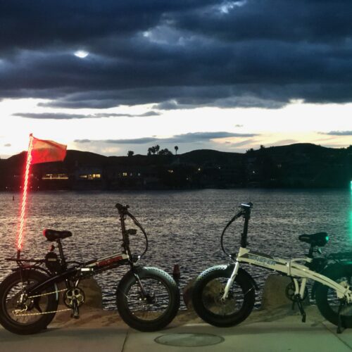
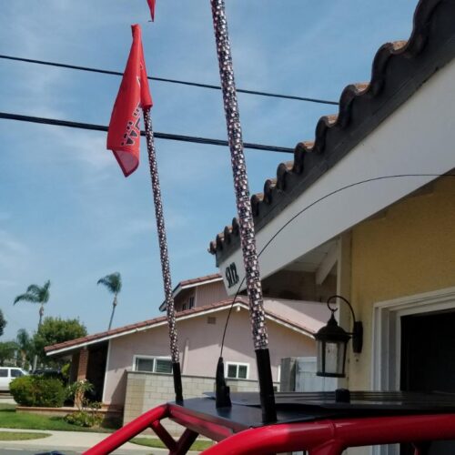
Camp Locator
To install you new camp locator you will need access to a 12 volt source on your trailer. In some instances you may be able to remove the top ball of your flag pole and place the lower rod portion in the opening and securing it that way (poles and holder flag pole). If the above does not match your current plag pole then you may attach following this description, To attach your camp locator to your flag pole take the lower rod and using 3 to 4 ziptys to the upper portion of the flag pole.
We have provided you with two Velcro straps to use to secure the wire on the flag pole itself. We recommend one every 10’ down from top.
Next you will need to attach power to 12 volt source, we recommend the battery on your trailer. The red wire will attach to the positive terminal of the battery and the black wire will attach to the negative terminal of the battery. Use the supplied alligator clips to clip onto the eyelets attached to you battery. If you would like, you can remove the alligator clips, and attach an eyelet to mount permanently to your 12volt source. There is a quick disconnect at the controller that will allow removal for storage.
If the Flag pole mount is in the rear corner of trailer you will need to provide wire to complete this run. We recommend a larger gauge wire such as a 14-16 gauge wire. With a run of 20-30 feet you will see a voltage drop over that distance. example: battery may be at 12.4V measured at the end of 30ft may have a voltage of 11.9V with a smaller gauge wire. Please remember that you have a 30 foot run up the pool so total you may have 50-60 ft of wire before the LED receive power. A voltage drop will decrease the brightness of the camp locator.
Please be aware that the telescoping flag poles will feed inside of each other. If flag pole prematurely collapses it may damage the wires feeding into the camp locator. In some cases electrical tape wrapped a foot or two down from the tip will prevent the top pole from sliding into the next section preventing damage to the wire.
When storing your camp locator use the supplied Velcro straps to bundle the wire and the locator together for nice and neat storage. Do not wrap the wire around locator, this will cause premature failure of the wire.
Warranty
WhipTech will stand behind its product for up to 1 year with Receipt or proof of purchase. This may and will include manufacture defects. Please understand that the RCA design plug in the bottom becomes A point that may suffer the easiest damage when handling the lighted whip off the car. Dropping the base on the ground and breaking the RCA is not covered as Manufactures defect. Please make sure that you have used your WhipTech car mount and have evacuated/blown out all the debris before installing your whip. A single grain of sand in the thread can cause galling and in some cases will not allow you to install or remove the lighted whip without using excessive force or tools. Situations like this that may cause damage to the threads and the base or the RCA will not be covered under warranty. Using another manufactures car mount or whip mount may lead to the voiding of the warranty. Rollovers will not be covered under the current warranty. We hope in that situation the only thing that takes a beating is the lighted whip. In both situations we will gladly rebuild that whip for you for $40 plus shipping to our shop, we will cover the ride home for you.
Please understand that offroading is a violent activity that you and your equipment may experience severe conditions. As we have done our best ability to account for most conditions we can not prepare for all of them. With that being said please understand that you may see some separation between the LED light strip and the clear center strip used to hold the LED strip up. Small separation in several places will be considered normal wear due to the nature of the constant whipping back and for the the whip. When an item bends there is always a long side and a short side, to allow this to happen the LED needs lengthen and shorten this is what causes small separation in some places. I understand that there is some gray area here but if you have any questions please contact us or send a picture of your whip and we will gladly respond. Due to this whipping movement that may lead to the development of small scratches on the inside of the lighted whip. Believe me we want these to look as good as the day they left the showroom floor and we do out best to keep them looking that way.
Any issues after that initial one year period with your WhipTech lighted whip contact us and we will be able to re manufacture your whip for 30$. You pay for shipping to us and we will cover it on the way home. Down time may vary depending on time of the year but we will do our best to get it back to you in a timely manner.